3D viewing is a difficult problem to master for beginners of webgl like me. Model matrix, view matrix, projection matrix, camara position, local coordinates, world coordinates, view coordinates, windows coordinates, left-hand coordinates, right-hand coordinates, etc. So many buzz words exist just to paint a point on screen! The key point is how the scene looks like from the point view of camera. So if we can visualize it(camera looking at the scene) correctly, we can get some deep insight into the mysterious 3D viewing. Let’s do it theoretically.
At first, i want to show you a graph which contains the essence of 3D viewing.
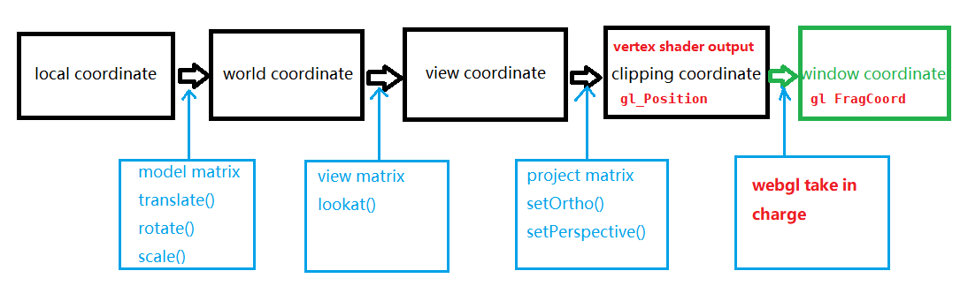
That is the normal process of setting up 3D models and viewing it. We use Mm, Mv, Mp to represent model matrix, view matrix, project matrix respectively, then gl_Position can be computed as:
1 | gl_Position = Mp * Mv * Mm * [original(local) position] |
The result of Mp * Mv * Mm is usually named as MVP matrix: Mmvp.
A clipping normalized cube with a range of (-1, 1) for each axis is used to cut out all the points whose gl_Position is outside of the cube. It is our job to compute gl_Position with all the matrices(or with no matrix as long as that gl_Position is inside the cube if you want to show your model). WebGL is responsible for the last step: get the final position in window coordinate, i.e. compute the gl_FragCoord. We normally just set the viewport and don’t care about it:
1 | gl.viewport(x, y, w, h); |
You can refer to the spec to figure out how it is computed.
Ok, preparatory work is done. Let’s shift to business. To visualize a camera looking at some objects, we need a second camera:
1 | camera2 looking at camera1 which is looking at some object |
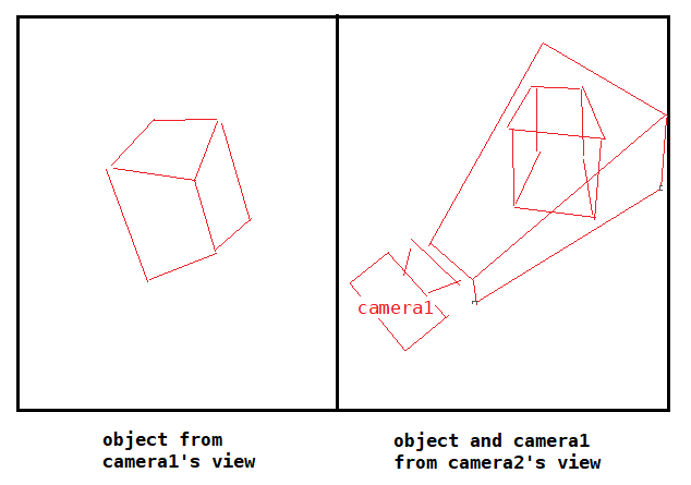
Two major steps are taken to do it:
Firstly, draw the left part: the object being looked at from camera1, use matrices as follows:
1 | Mmvp = Mp1 * Mv1 * Mm1 |
This step is easy to understand.
Secondly, draw the right part: the object & camera1 being looked at from camera2:
Draw the object:
1
Mmvp = Mp2 * Mv2 * Mm2
No much to say.
Draw camera1:
1
Mmvp = Mp2 * Mv2 * (inverse of Mv1)
Why the
model matrixof camera1 from the view of camera2 isinverse of Mv1? Well, when setting up the camera, we can move the camera or move the scene. Both are inverse process of each other: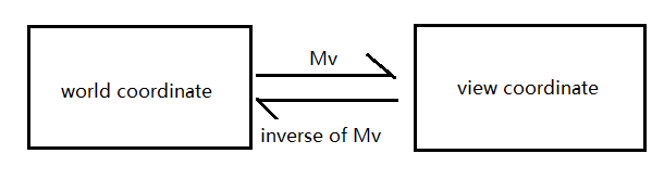
Draw the frustum which is transformed to a normalized cube:
1
Mmvp = Mp2 * Mv2 * (inverse of Mv1) * (inverse of Mp1)
It is the most difficult part to understand. We want to know the cube’s position in
world coordinatewhich the model matrix represents. We should firstly ask where does the normalized cube come from? Yes, it comes from aMVPtransformation performed by camera1: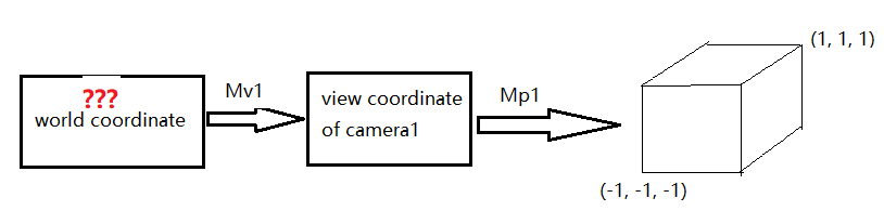
So we deduce reversely and get model matrix:
(inverse of Mv1) * (inverse of Mp1).
Game over theoretically! If you want a real and practical example, please refer to this great article.